The overriding principle of the design
Tower Bridge was designed, like an air traffic control (ATC) system, to deliver an extremely high level of availability – basically the probability that the bridge would be capable of operating when required. I’ve estimated the availability to be of the order of 99.995%. Everything necessary to operate the bridge was duplicated.
The engines which lifted the bascules were housed in four engine rooms in the piers, just below street level. There were two engines in each engine room. These were hydraulic engines, worked by water at a pressure of 700 psi. This is an enormous pressure, equivalent to the pressure 1600 feet below the surface of the sea and sufficient to crush a WWII U-boat.
Steam plant – boilers and steam-operated hydraulic pump sets
The hydraulic pressure generation plant occupied five of the arches under the southern approach road.
Two of the arches housed the four Lancashire boilers used for steam generation, two boilers per arch. The boilers produced saturated steam at a pressure of 85 pounds per square inch. At any time, two boilers were in use, with the other two kept in reserve.
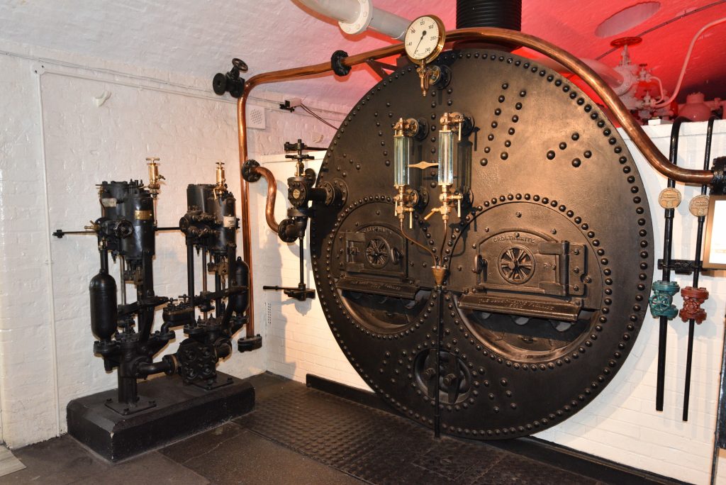
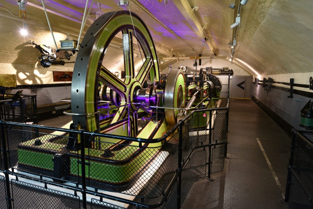
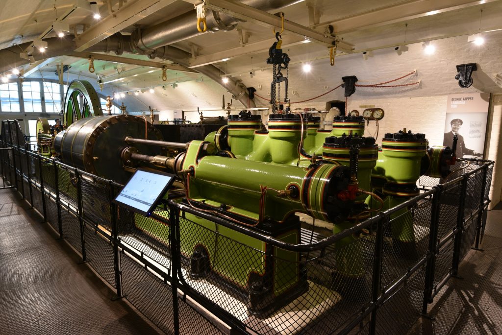
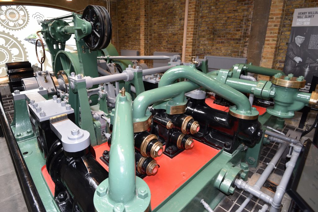
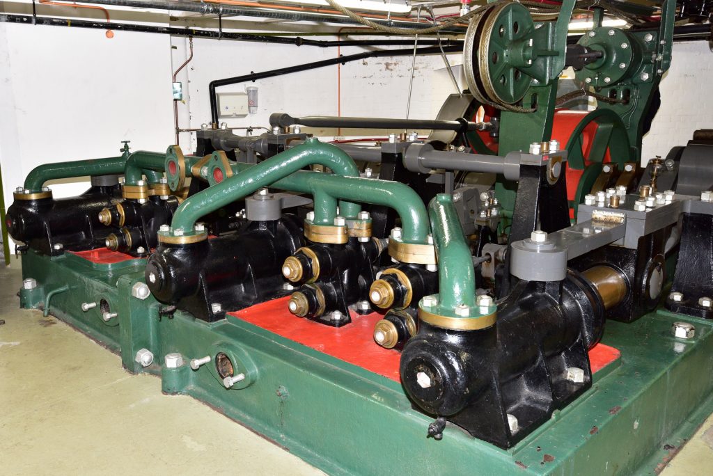
Two arches were occupied by the horizontal tandem steam engines and pumps used to generate the hydraulic pressure for the bridge. Each engine was rated at 360hp and had a high pressure cylinder 19¾ inches in diameter and a low pressure cylinder 37 inches in diameter on each side of the engine, each low/high pressure cylinder pair being coaxial and driven by a single piston rod. Each side of each engine drove a force pump with a diameter of 7¾ inches and a stroke of 38 inches. Each tandem engine had sufficient power and pumping capacity to power the hydraulics of the bridge. The engines were governed at 15 rpm and one engine was normally ticking over at 4 rpm to top up the supply of high-pressure water.
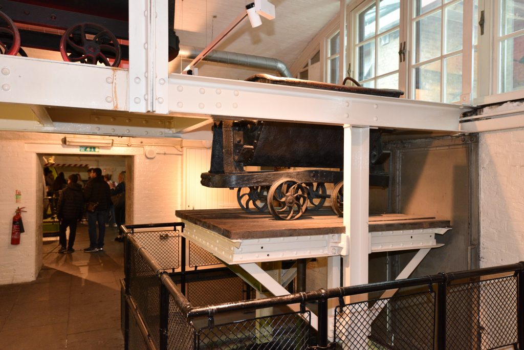
In between the boilers and the engines was an arch occupied by a coal store. The coal was lifted from barges moored against the southern abutment by means of a hydraulic crane and transported to the coal store on small tipping wagons running on rails and pushed by hand. An elevated track running down the centre of the coal store was used to distribute the coal in the store, the wagons being lifted onto the track by a hydraulic hoist.
Hydraulic accumulators
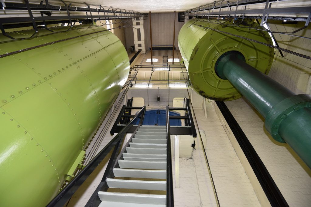
The raised weight hydraulic accumulator was invented by Sir William Armstrong. Its purpose was to store high-pressure water for use in hydraulic machinery. Prior to the invention of the accumulator, it was common practice to build very tall towers containing water tanks as a means of generating hydraulic pressure. These towers would typically be over 200ft tall. However, the pressure of a 200 foot column of water is relatively modest, just 87 pounds per square inch.
A raised weight accumulator does not need to be very tall yet it can provide pressures of 700 – 850 pounds per square inch very easily. The principle is very simple. A vertical pipe containing the hydraulic fluid (water in the case of Tower Bridge) is closed at the top by a piston which is weighted. A large volume of pig iron is held in a large cylinder which is free to move between vertical guide rails.
Water is pumped into the high pressure water pipes. When the pressure multiplied by the piston area equals the weight acting on the piston, the piston begins to rise. Thus it is simple to design an accumulator to achieve any desired working pressure. When the accumulator is at the top of its stroke, the pumps can be switched off and high-pressure water remains available on demand, the pumps being used sporadically to top up the volume of high-pressure water available.
At Tower Bridge, there are two accumulators in an accumulator house just to the east of the plant rooms. These have a pipe/piston diameter of 20 inches and a stroke of 35 feet, storing between them up to 153 cubic feet of high-pressure water.
Each pier had two further accumulators, in accumulator chambers at each end of the pier, each with a pipe/piston diameter of 22 inches and a stroke of 18 feet. This enabled each pier to store up to 95 cubic feet of additional high-pressure water.
The maximum volume of high-pressure water which could be stored in all six accumulators was about 350 cubic feet. I’ve confirmed by calculation that the bridge could certainly be opened and closed using just the high-pressure water stored in all six accumulators. (Some sources state that the bridge could be opened and closed twice using just the high-pressure water stored in fully-charged accumulators.) I’ve also calculated that it would take only 5 minutes 37 seconds to refill exhausted accumulators.
Pressurised water distribution
The system for distributing high-pressure water to the piers and the engine rooms within them was duplicated, the supply pipes to operate the engines in the Middlesex pier routed up the Surrey tower, across the top of the east footway and down the Middlesex tower.
Hydraulic engines
Each pier has two engine rooms. There were two 3-cylinder, single-acting hydraulic engines of unequal power in each engine room. The design intention was that, in normal circumstances, one small engine would be capable of lifting a bascule. In a wind pressure of 56 pounds per square foot (unheard of at the location of Tower Bridge), one small and one large engine acting together would be capable of lifting the bascule. This meant that the small and large engine at the other end of each pier would provide a massive power reserve of 100%, even in the very worst case.
In each engine room, the small and large engines sat side by side, with their crankshafts on the same centreline, the smaller engine being situated towards the end of the pier and the larger engine closer to the centre of the pier. Each engine had a 15-tooth pinion rigidly attached to its crankshaft which engaged with a 41-tooth pinion on an intermediate shaft running behind, and connecting, the two engines. The two 41-tooth pinions were fitted with manually-operated dog clutches, enabling one or both engines to be disengaged from the intermediate shaft for maintenance or repair purposes. A 13-tooth pinion on the end of the intermediate shaft closest to the bascule engaged with a 29-tooth pinion on the final drive pinion shaft, effecting an overall step down gearing of 6.097:1 between the engine crankshafts and the pinion drive shaft.
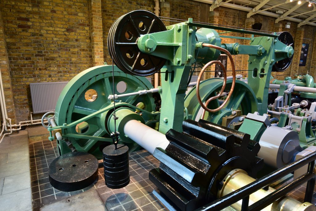
The image below shows the crankshaft end of the same large hydraulic engine. A section of the intermediate shaft and one of the dog clutches is clearly visible. The braking system is a prominent feature. A large brake wheel is fitted to the crankshaft against which two brake blocks work. When the engine is required to operate, the brake blocks are forced away from the brake wheel by a hydraulic cylinder. When the brake needs to be applied, or if hydraulic pressure is lost, the brake blocks are forced against the brake wheel by means of a heavy weight attached to the end of a steel wire wound around the two high-level grooved wheels on the brake gear.
Thankfully, all four small hydraulic engines were preserved and remain in the engine rooms in the piers.
Bridge control
A control, or driver’s, cabin was built on the east side of each pier and a watchman’s cabin constructed on the west side of each pier. Stairs in each cabin led down to the engine room below.
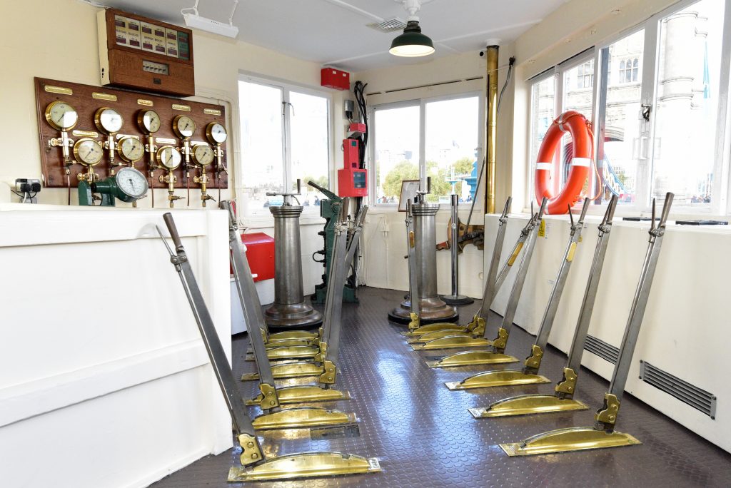
Two lever frames similar to those in railway signal boxes were provided to control the hydraulic machinery, together with mechanical interlocking frames below the floor of each control cabin. The interlocking frames prevented, for example, any hydraulic engine from being operable until the pawls and resting blocks had been withdrawn. The nose (or locking) bolts were controlled from the south control cabin only.
Semaphore signals, indicating to shipping during daytime whether the bridge was open or shut were mounted on top of the cabins, operated manually by levers in the cabins. Four red and four green lights in both upstream and downstream directions performed a similar function at night.
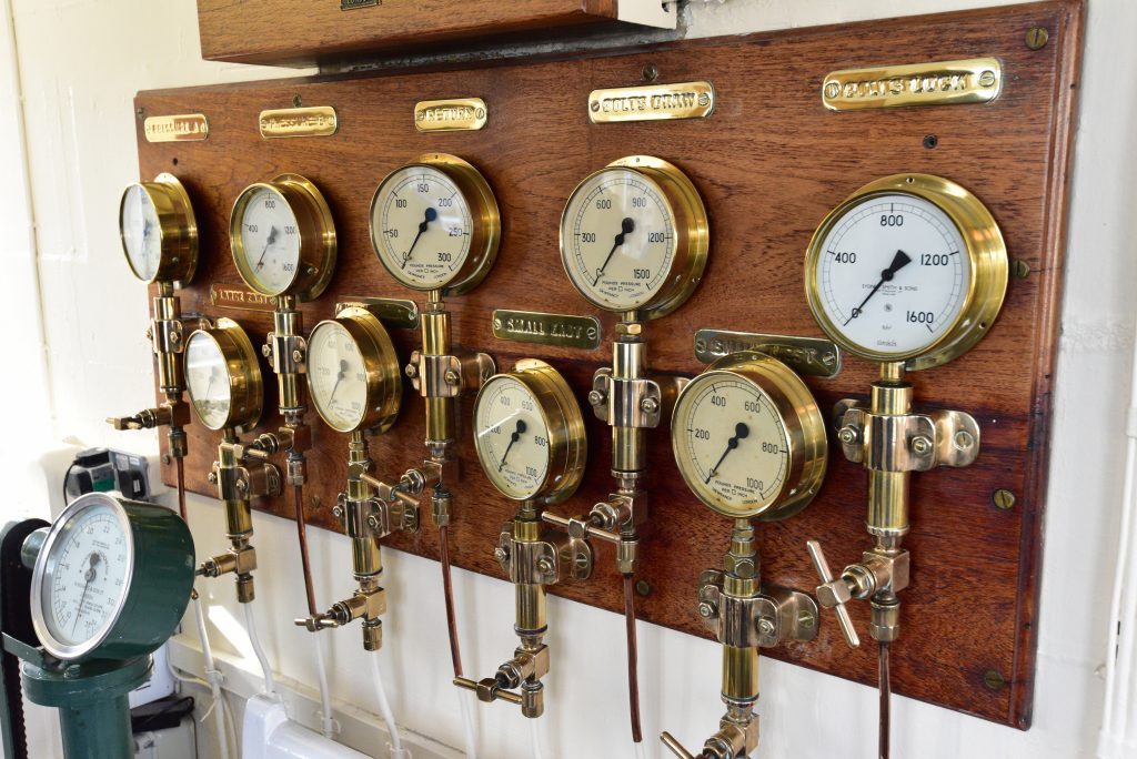
The image below shows the inside of the south control cabin today, still containing its original equipment. The bank of gauges on the wall showed the driver the pressure available to operate the machinery from the two separate high-pressure water supplies (A and B), plus the pressure in the return/exhaust pipe. They give tangible evidence that the nose bolts are either locked or unlocked, and show the pressure admitted to the chosen engine(s) by means of the regulator valve.
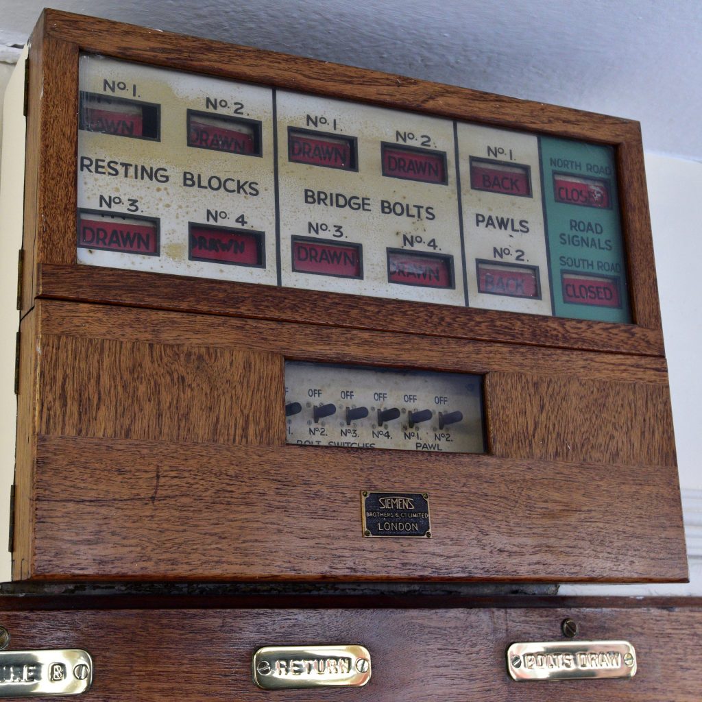
Above the water pressure gauges is a tell-tale board, showing the position of the Surrey resting blocks and pawls, the nose bolts, and the road signals at both ends of the bridge.
A telephone system for communicating between control and watch cabins, and between control cabins and the engine room under the southern approach was installed by Messrs. Spagnoletti and Crookes. There was also a system of signalling bells and a set of bell codes, again inspired by railway signalling practice.
The procedure to operate the bridge was as follows. The Bridge Master would have decided which engine room on each pier was to be used that day and the engine drivers would have selected either the large engine or the small engine in the chosen engine room by means of the levers. Clutches would not normally be operated on a daily basis, the three unused engines being kept in gear and allowed to run idle. As the bridge was required by Act of Parliament to lift on demand, a watchman would be on look-out at all times in all four cabins and a driver would be available in each control cabin. The approach of a vessel would be signalled by a bell code. The Head Watchman would decide when to instruct the clearance of the bridge. On his order, the City of London policeman on duty on each pier would operate the traffic signals and clear traffic from the moving leaves. Watchmen would clear foot passengers from the moving leaves and close barriers across the road way and the pavements. On the Head Watchman’s signal, the drivers would retract the pawls and resting blocks and the driver on the Surrey pier would withdraw the nose bolts. The driver on the Middlesex pier had no way of knowing when the nose bolts had been withdrawn, so the Surrey bascule always lifted first, the driver in the Middlesex control cabin operating his starting valve when he saw the first movement of the Surrey bascule. Once the bridge was as open as necessary, the semaphore signals or lights for shipping were changed to advise the master of the approaching vessel that he could proceed. The drivers would apply the brakes on the engines being used. Normally, the moving leaves were not opened fully, this being reserved for “a salute of honour”. The procedure was essentially reversed for lowering the bascules.
Hydraulic lifts
The lifts in the main towers were each operated by duplicated hydraulic cylinders. Lifting ropes and counterweight ropes were duplicated also, and interlocking gear prevented movement of a lift until both inner and outer doors were closed.