Introduction
This website describes the design of each different type of bridge at the site in general terms. A detailed description can be found in the Haynes Tower Bridge Operations Manual.
The masonry arch viaducts
The Middlesex (north) masonry arch viaduct contains accommodation for the Tower of London, including a guardroom (now a restaurant). It is also the means of access to inspect the anchor ties and girders of the Middlesex suspension bridge. The two anchor girders are held in place by an enormous block of concrete below the piers of the viaduct arches.
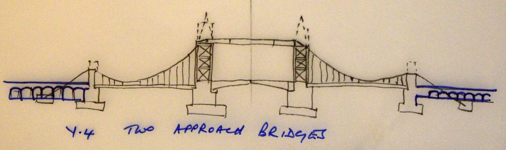
The Surrey (south) masonry arch viaduct contains accommodation for the boilers, coal store, steam engines and pumps needed to generate the hydraulic pressure to operate the hydraulic engines in the piers. It is also the means of access to inspect the anchor ties and girders of the Surrey suspension bridge. The anchor girders are also held in place by an enormous block of concrete below the piers of the viaduct arches.
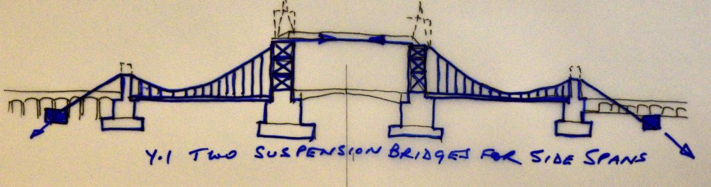
The suspension bridges
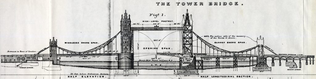
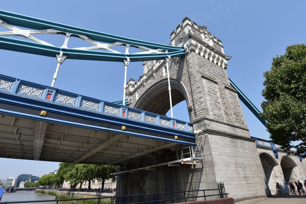
There are two suspension bridges. On each suspension bridge, the load of the roadway is suspended from four “chains”, two on either side of the roadway, the chains taking the form of braced steel girders which are stiff enough to prevent local deflection of the roadway under traffic loading. The chains are unequal in length, this design decision being taken in the light of the different heights of the main towers and the abutment towers.
The main towers comprise steel superstructures, the weight and imposed loading of which is carried on masonry piers which are massive in themselves and which also bear the applied load of the bascule bridges, the road bridges which span the bascule chambers, the high-level footbridges, and the masonry which surrounds the steel towers.
The steel superstructure of each tower, which is of all-riveted construction, comprises four octagonal steel columns, one in each corner. The columns are rigidly attached to three substantial landings, and provided with cross-bracing to withstand wind loading transmitted from the external masonry “cladding”. The steel roof structure of each tower is supported by a further landing which is mounted on four steel stanchions, positioned above the columns.
Each abutment tower also comprises a steel superstructure and an outer masonry skin, the weight of which is carried on a substantial brick pier, sitting on a concrete foundation. The steel superstructure of each abutment tower also comprises four octagonal steel columns, one in each corner, stiffened longitudinally by horizontal and diagonal girders and transversely by arched steel box girders above the roadway.
Below the approaches at each end of Tower Bridge are two massive steel anchor girders, deep underground and with a great mass of concrete holding them in place. These four anchor girders resist the tension in chains and ties induced by the suspended load of the two suspension bridges.
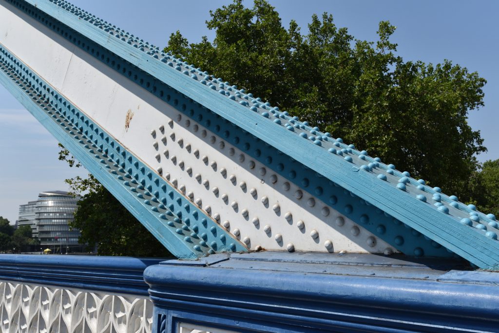
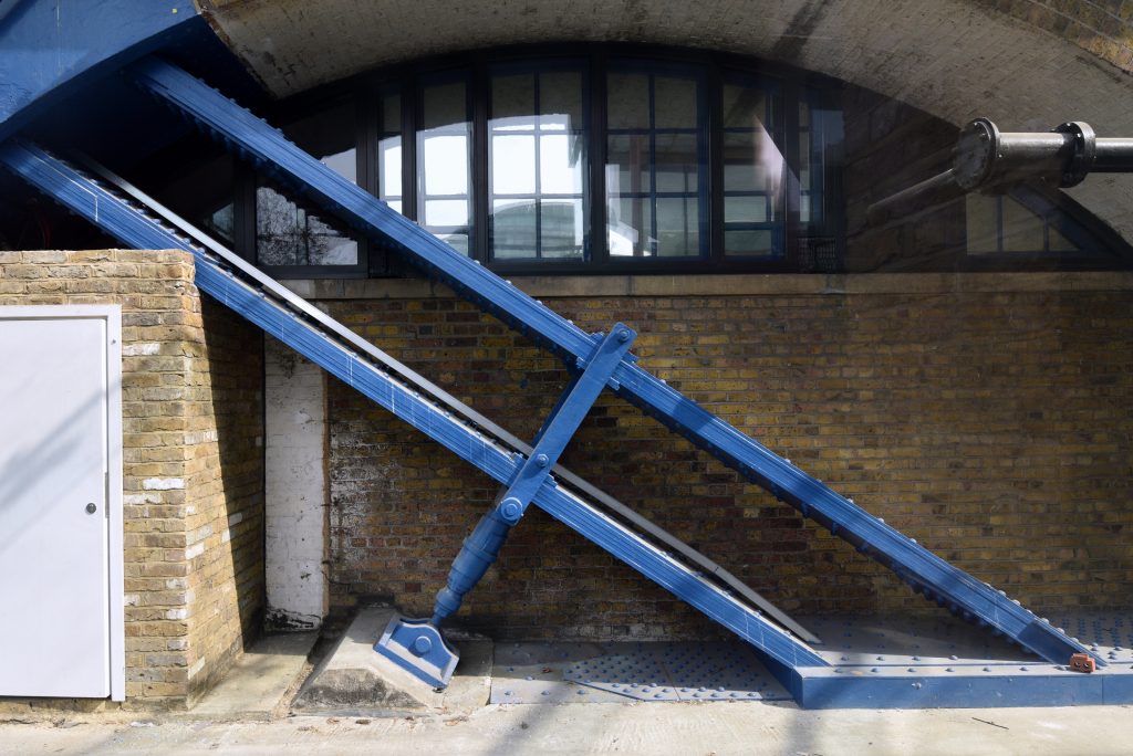
Moving from right to left in the image below (which shows the west side of the bridge), the tensile load is first carried by the west Surrey land tie which is a straight, sloping riveted steel girder, taking the form of a box girder above the parapet and a pair of flat ties of rectangular section, below ground. As the west Surrey land tie approaches the west Surrey anchor girder, it branches to provide three points of attachment to the anchor girder, the attachment being by means of riveting.
At the landward side of the Surrey abutment tower, the west Surrey land tie connects via a pinned joint to a horizontal link comprising two parallel thick steel plates made up of multiple plates riveted together. The river end of the link is pinned to the west Surrey short chain. Below the two pinned joints, the link is supported on rollers (or “rockers”) which transmit vertical load to the two westward octagonal columns of the Surrey abutment superstructure and provide the means whereby movement caused by bridge loading and thermal expansion or contraction is accommodated.
The next pinned joint links the long and short west Surrey chains above the suspended roadway.
The west Surrey long chain is pinned to the west high-level tie above the west landward column of the Surrey main tower. The end of the tie is supported on rockers which transmit the vertical load to the west landward column of the Surrey main tower.
The west high-level tie carries the tensile load to the Middlesex main tower. The arrangement is similar on the Middlesex side of the bridge. However, the form of the Middlesex land ties below the bridge parapet differs from that on the Surrey side. The means of connection of the Middlesex land ties to their anchor girders is also different.
The chains and ties were tensioned simply by removing the temporary staging and support girders below the suspended roadway sections when bridge construction was complete.
The Tower Bridge Operations Manual contains force diagrams showing the forces acting at the various points of the structure both in 1894 and in the present day.
The bridges over the bascule chambers
The roadway over each bascule chamber is carried by a simply-supported steel bridge comprising six fabricated steel girders supporting concrete-filled transverse steel trough plates. The road was originally finished using wooden blocks.
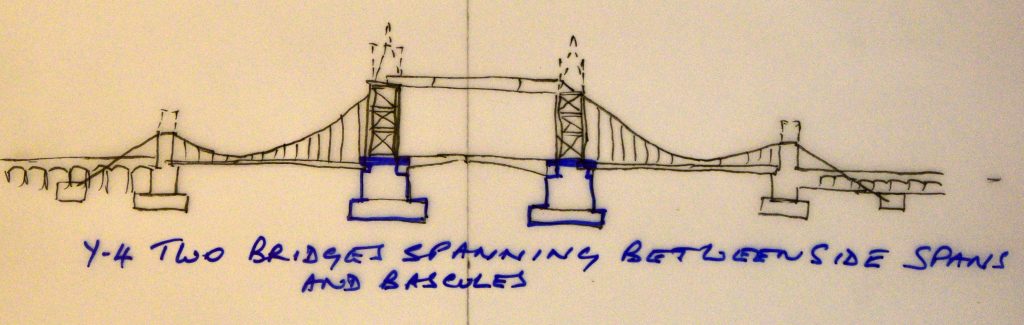
The bascule bridges
Bascule is a French word meaning seesaw. The principle is a very simple one. A perfectly-balanced bascule, though it might weigh almost 1100 tons, does not require a massive amount of motive power to operate, once the initial inertia has been overcome. Of course, wind pressure on the bascules is a major factor, and the original machinery for Tower Bridge was designed to operate the bridge even in an extreme wind pressure of 56 pounds per square foot.
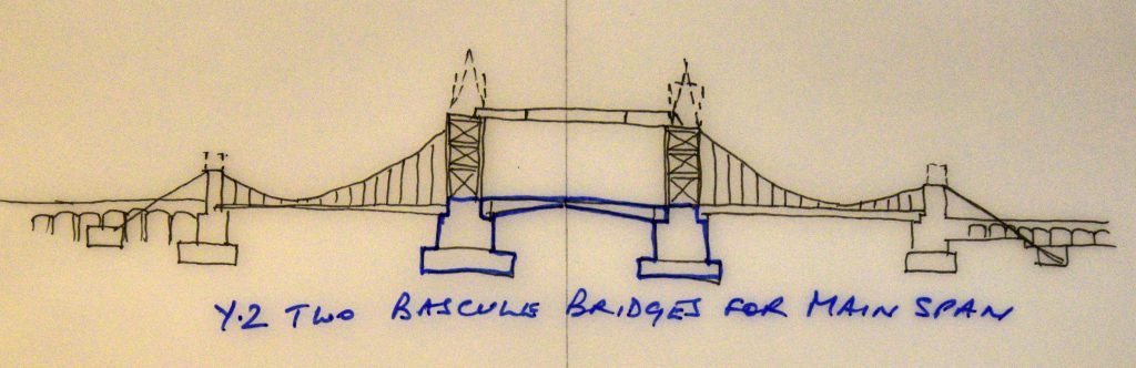
The diagram below is a modern copy of a diagram included in John Wolfe Barry’s 1894 lecture on the bridge.
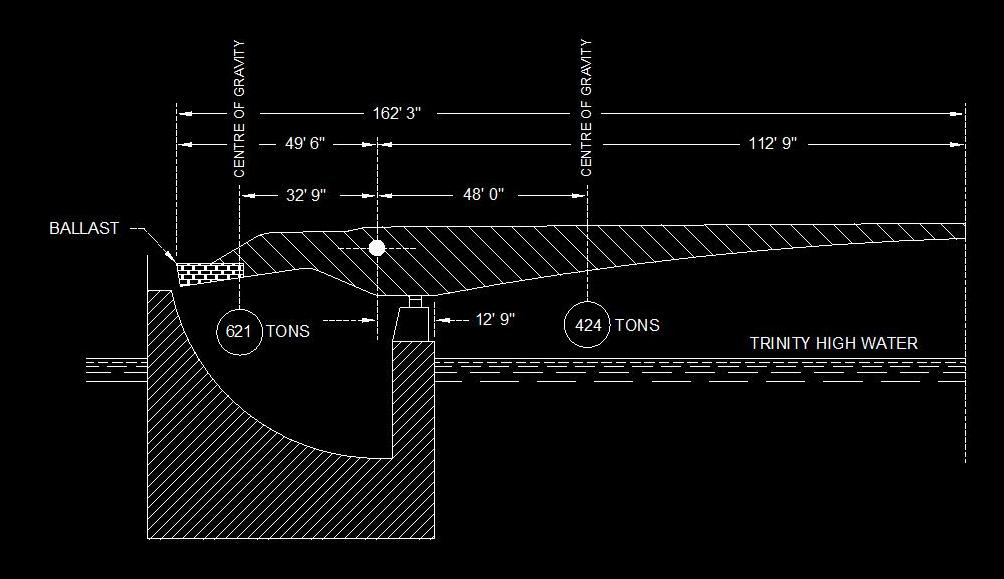
The bascules were designed such that, when closed, they give the opening part of the bridge the appearance of a shallow pointed arch. When open, each moving leaf sits inside the vertical line of the side of its pier, making the full channel width of 200 feet available, with a clear headway of 140 feet. Each bascule moves through a maximum arc of 82º, but the bridge is seldom opened to this extent.
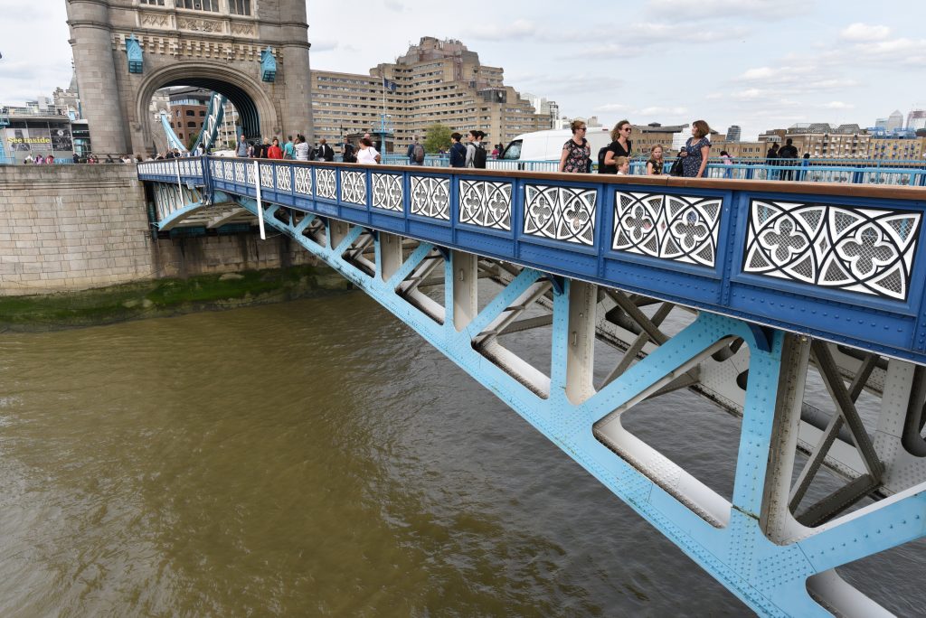
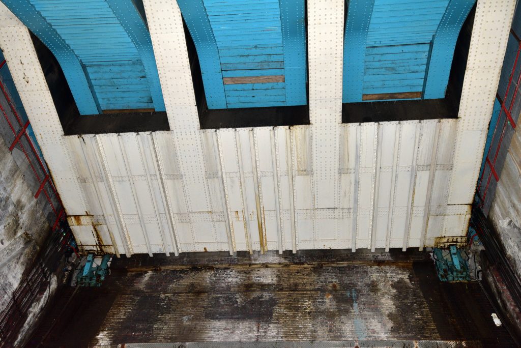
The image below is a photograph taken from the bottom of the Surrey bascule chamber, showing the rear of the Surrey moving leaf. The ballast box, sitting below the fixed girders, and the two pawls supporting the rear of the leaf are clearly visible.
The footbridges
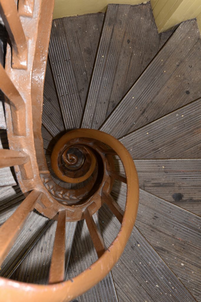
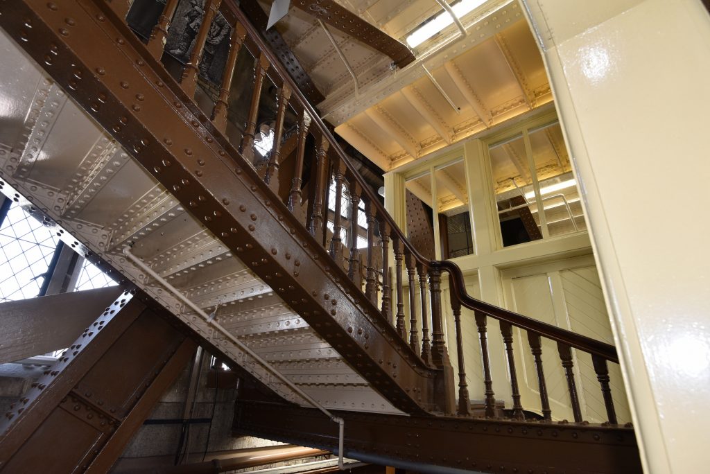
The purpose of the walkways was twofold. Firstly, they were designed to provide a means for foot passengers to cross the bridge when the bascules were raised. When first completed in 1894, the bascules were raised about 17 times per day. The following year there was a small increase, the bascules being raised about 20 times per day. So interruption of vehicular and foot passenger traffic was frequent. It could also be prolonged, if several vessels followed each other into, or out of, the Inner Pool. The average interruption to traffic was six minutes and the longest interruption to traffic during the first two years of operation was 36 minutes. Two sets of stairs (one up, one down) in both main towers were accessible to the public between sunrise and sunset for passengers in a hurry, but there were 206 steps up to the walkways and the same number down on the other side. These staircases have changed very little. There were two circular staircases in each main tower between roadway level and the first landing. Beyond this level, free from the constraints imposed by the bascule quadrants and the arch, the stairs were implemented as straight flights.
The secondary role of the footbridges was to support, and provide protection for the two high-level ties of the suspension bridges, which are positioned at low level inside the outer girder of each footway.
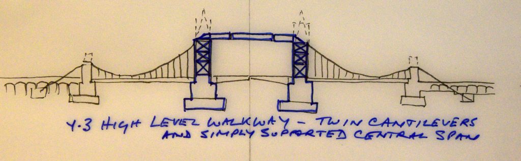
Each footbridge, footway or walkway consists of a simply-supported central section slung between two cantilevered end sections, one attached to the Middlesex superstructure and the other to the steelwork of the Surrey main tower.
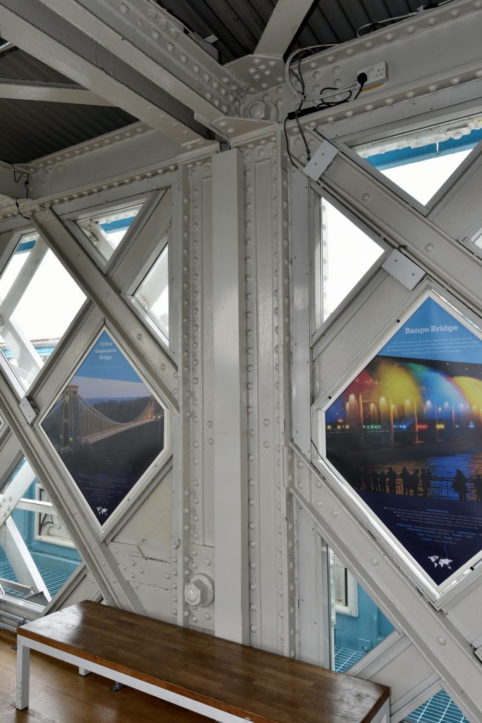
Five inch diameter pins near the ends of the top booms of each cantilevered section of footway carry forged steel links which connect to similar 5 inch diameter pins in the vertical ends of the girders of the central section. Inner and outer girders are 12 feet 10 inches high and feature a double lattice of flat bars for the ties and channel bars for the struts. The centres of the inner and outer girders are 12 feet apart, giving a clear width of 10 feet for foot passengers.
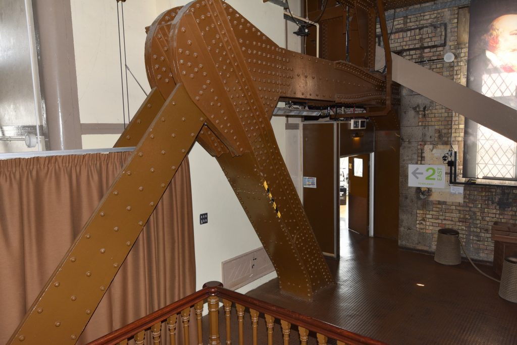
The image below shows the east inner cantilever of the Middlesex main tower. This is one of my favourite parts of the bridge and is a wonderful example of “form ever following function”. It would make a formidable opponent for a tug-of-war team.
The inner cantilever is securely attached to one of the main cross girders, which sit on top of the north and south third landing girders in each tower. This particular cross girder extends a little beyond the main landing girder to provide direct support for the end of the inner cantilevered footway girder.
The image below shows the junction of a cantilevered footway section with its central section. The hex nuts, 4½ inches across flats, which hold the suspension pins in place are clearly visible.
Each high-level tie is 301 feet long between the centres of the holes in the eyes, and each tie weighs 120 tons. Each tie was supported by 1½ inch diameter rods, suspended from the top boom of the outer footway girder. At their lower ends, the suspender rods attached to a cradle bolted to the top of the tie by means of one of the 1 inch fitted bolts in the top row of bolts connecting the two halves of the tie together. The bottom edge of the high-level tie was about 6 inches from the “floor” of the bottom boom. The suspender rods were spaced at intervals of about 12 feet.
The image below is a simple force diagram for an inner fixed footway girder, as originally constructed in 1894. Dimensions are in feet and weights are in tons.
Half the weight of the cantilevered section of footway acts halfway along the inner girder, and one quarter of the weight of the middle section of footway acts at the end of the inner girder. None of the weight of the high-level tie is carried by the inner girder.
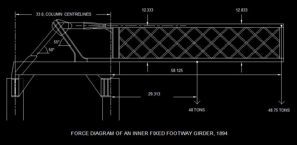
An analysis of the forces in the structure show that:
- The horizontal pull exerted by the cantilever is 287.8 tons,
- The tension in the shore-side angled member is 167.8 tons,
- The compressive force in the river-side angled member is 156.9 tons,
- The vertical weight acting on the river-side column is 225.3 tons.
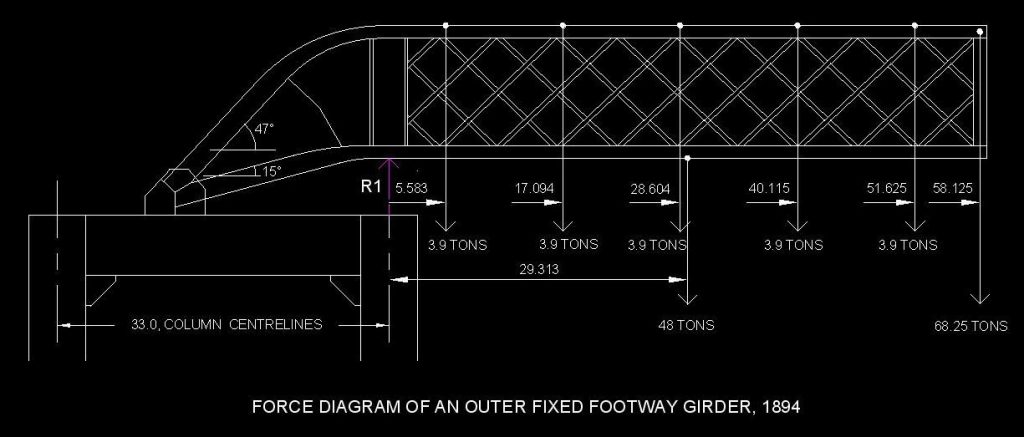
The image below is a simple force diagram for an outer fixed footway girder, as originally constructed in 1894. The 3.9 ton forces are the weights borne by the original high-level tie suspender rods.
The catenary wire suspension bridges
In circa 1960, high-level tie suspension bridges were installed, relieving the outer footway girders of the weight of the ties. These transfer the dead weight of the high-level ties to the superstructure of the main towers. It was a neat and effective solution and one which is probably unnoticed by most tourists visiting the bridge, the internal catenary wire looking very much like a handrail.
Occasional cross-bracing and the links suspending the middle footway sections from the cantilevered footway sections prevent a single catenary cable solution, so two cables were used to support each high-level tie, one inside the footway and one outside. The load of the tie is carried by 12 pairs of suspender rods. These are spaced approximately every 12 feet along the footway. Each suspender rod terminates in a cable clamp at its upper end and holds one end of a carrier at its lower end.
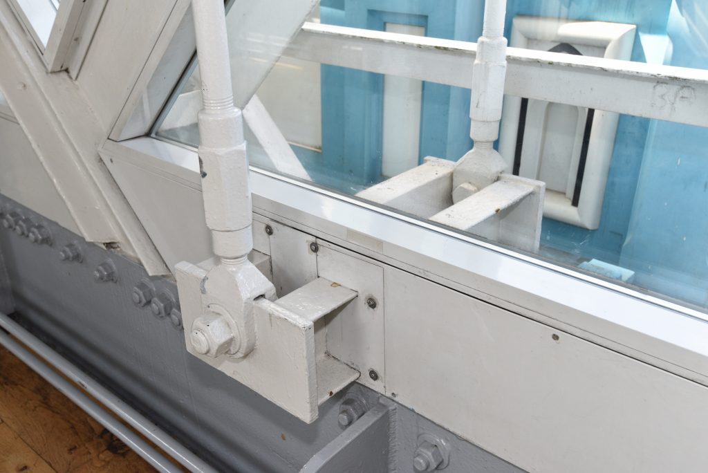
The image below shows the connection of a pair of suspender rods with their carrier. Adjusters provide the means to ensure that the suspended high-level tie is straight and level.
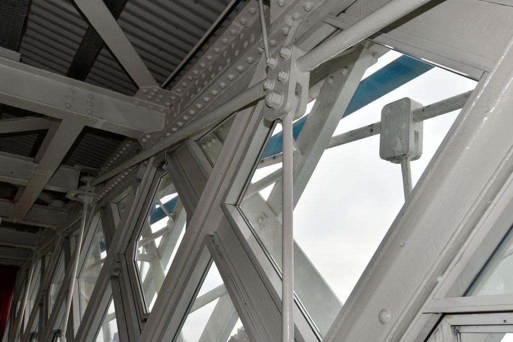
The image below shows the cable clamps connecting a pair of suspender rods with their catenary cables. The photograph also shows the ingenious means by which both a catenary cable and a cable clamp are taken through a roof beam.
The image below shows a simple force diagram for a single high-level tie suspension bridge, comprising two catenary cables. The angle at which the cables meet the superstructure of the towers is estimated at 12 degrees.
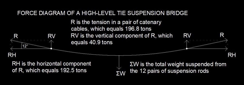
We know that the cables were each tensioned at 100 tonnes (98.421 long tons), so R = 200 tonnes or
196.842 tons.
RV = R*sin(12º) = 40.93 tons.
ΣW = 2*RV = 81.86 tons.
RH = R*cos(12º) = 192.54 tons.
This is the downside of this suspension bridge design, which had to deploy a very shallow angle of catenary. This means that each main tower is subjected to a horizontal force of 385.1 tons acting at the level of the cable anchorages, ie circa 217 feet above the base of the pier foundations.